Best new updated step by step of LAquis SCADA is in this link:
LAquis SCADA is a supervisory control and data acquisition software to work in the industrial control system (ICS) or in the distributed control system (DCS). From data acquisition to applications development. This is a small introduction on how to start using this system.
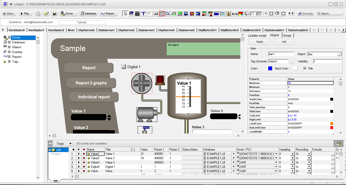
The SCADA system main screen for development, is divided into two parts: the bottom where there is a spreadsheet with the SCADA system tags and the top panel where the HMI visual objects are placed. In spreadsheet IN and OUT points are defined. This points came from the industrial devices like programmable logic controllers (PLC), modules, human machine interface, etc..., Equipment, variables, files, formulas, scales or other properties and user defined properties for each case.
On the panel, visual HMI objects can be used both for the development of specific HMI SCADA system systems via script and also for simple accompaniment of a data acquisition. Each HMI object can be related to a defined PLC SCADA tag in tag sheet.
When setting a database at the software in spreadsheet tags, you can generate SCADA system reports, analysis, and charts with system data stored through the "Reports" menu.
To start a development of a new application at the SCADA system click "New". A window appears with several models that generate predefined applications that can be changed as needed.
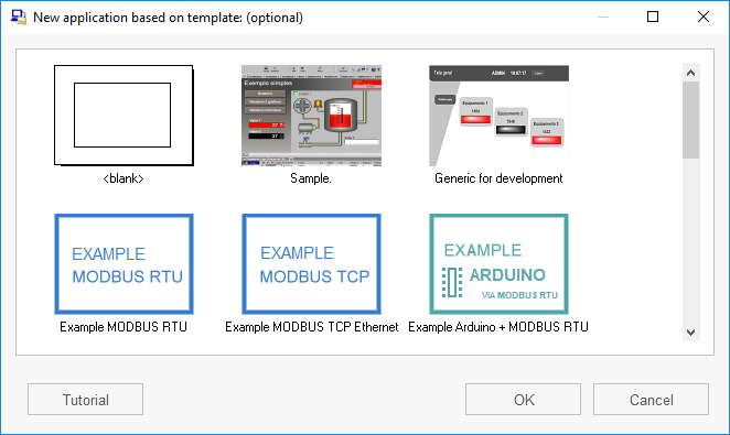
Follow the itens: below to use the system, clicking “New”, select <blank>, click OK, type a name and save.
SCADA system LAquis 5 first basic steps:
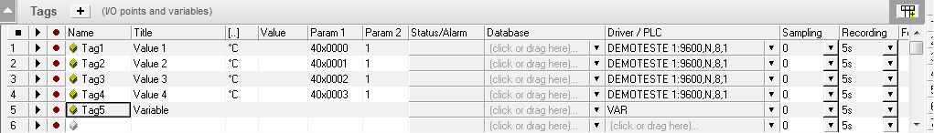
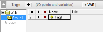
Set I/O points in SCADA system tags spreadsheet at the bottom of the main screen. These tags can be generic or physical equipment variables from the industrial network. The tags spreadsheet contains properties to define what will be read or written in the industrial equipment network. Some of the main properties are: Name, Title, Value, Unit, Driver / PLC, Database, Param1, Param2, etc .... Each property can be a column in this PLC tags spreadsheet. Choose the equipment driver to be used in the Driver / PLC column. The driver can be set by dragging the mouse pointer with the left button on the Driver / PLC column, or by clicking on the Driver / PLC column title to select all PLC tags desired at the system group.
When you release the mouse button, the window for selecting the driver will be shown:
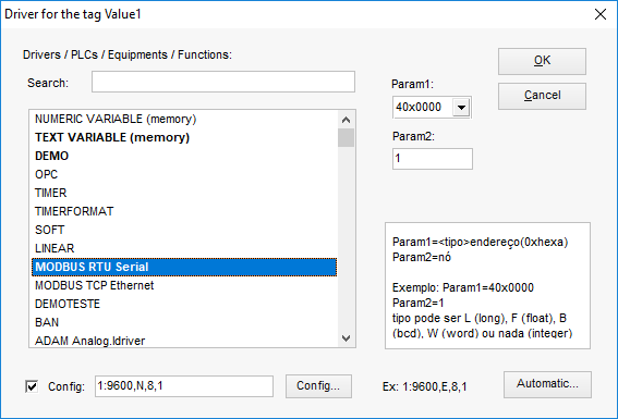
The driver to be chosen depends on the equipment (hardware / PLC) used with the SCADA system.
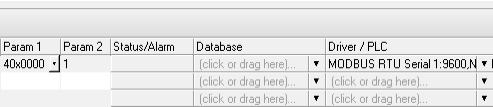
To simulate a device via software use, for example, the driver DEMO. To communicate with a device that uses the protocol "MODBUS RTU" then choose the driver MODBUS RTU. The Param1 will be the register address and Param2 will be the equipment node number (Example: Param1 = 400001 Param2 = 1.). See the MODBUS parameters description.
Set up communication (port, speed, timing, etc ....) on Config at the driver's window.
The following window will appear for serial port settings:
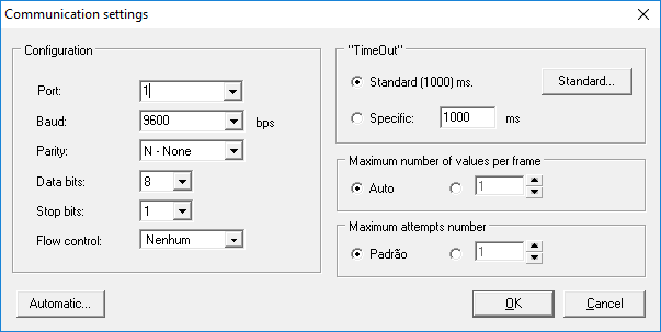
Set the communication parameters. Example for serial port COM1: 1:9600,N,8,1. (serial port 1, 9600 baud, no parity, 8 data bits, stop bits 1).
To use OPC in SCADA system, the select OPC driver, click on "Config". A window will appear to define the ProgID and Item ID. Optionally, for remote connections, type the IP of the server in the Server field:
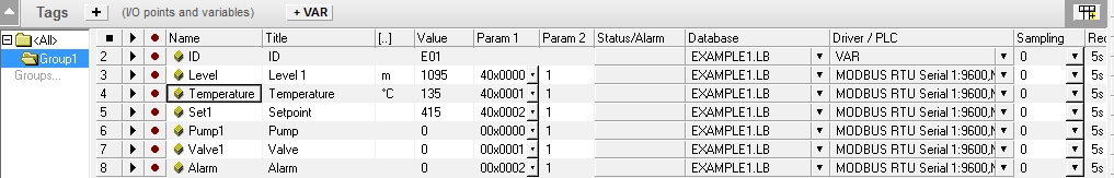
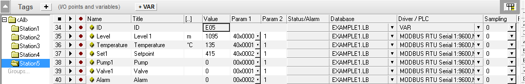
In this case, name (Tag1), title (Value 1), unit (° C), Param1 (40x0000) and Param2 (1):
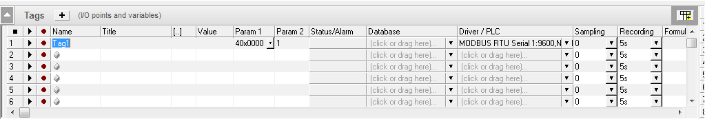
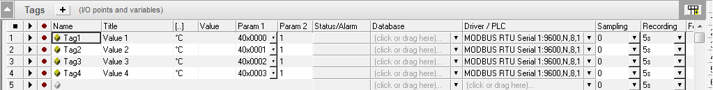
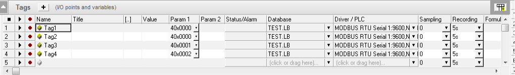
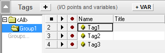
Example with four SCADA tags: (four first Holding registers will be read of equipment node 1 through Modbus protocol)
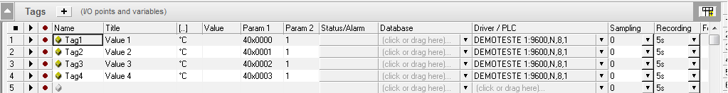
For simulation, it can be used DEMOTESTE or DEMO driver:
To start reading the values and test communication click on "Play" - Start application. Values in SCADA system will be shown in Value column. If there is a communication error, an "ERROR" message will appear in this column, and at the "Status" column.
To disconnect the communication, press the button "Stop" - Stop application.The tag may be also a variable for generic purposes. Use, for example, the VAR driver.
Each tag in SCADA system has properties that can be customized: alarms, formulas, limits, etc ...
Ex:
Tag1*Tag2 ' Multiplying two tags.
Tag3/7 ' Divide by 7
*0.1 'Multiply by 0.1 at reading (IN) and divide by 0.1 on write (OUT).
*Bit(0) ' Returns bit 0
To access formula options click on the button at the side of the formula column.
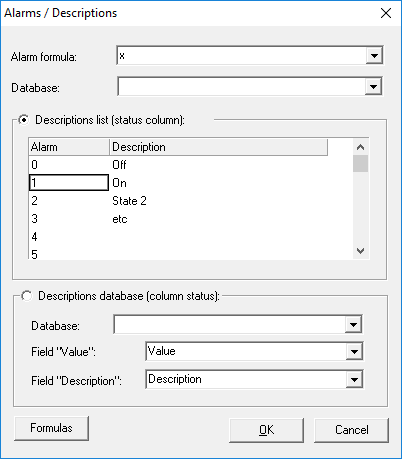
Alarm:
Click on the button at the right side to set alarm functions for a tag.
It can also be used to create descriptions for each PLC SCADA tag value. Example:
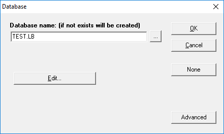
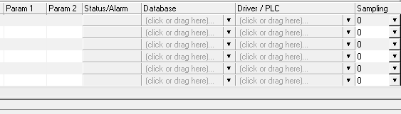
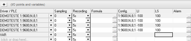
Data acquisition in SCADA system tags can be recorded to a file (database). Click on the database column. The database can be set by dragging the mouse pointer with the left mouse button on the database column (like it was done with the driver), or by clicking on the title of database column to select all SCADA system tags at the software group.
In this example, the values of the four SCADA tags will be stored in TEST.LB database:
The time interval in which the values are stored is set in the Recording column.
Note: by default, the system data are recorded in sub-folder "dados" inside the main application folder. To change the database settings using the menu item "Reports" - "Edit Database".
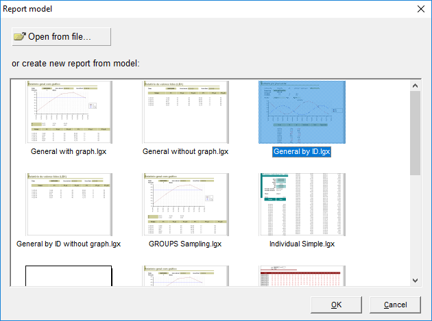
With some data already recorded in database it is possible to create SCADA system system reports.To generate a system report with the SCADA system recorded data, click at the menu Data and Reports - Open (or insert a button HMI object in the panel and click "Show this button's report" - as explained in step 3). At the first time, in this stage of development, a window will be shown for choosing a system report template (that can be customized later):
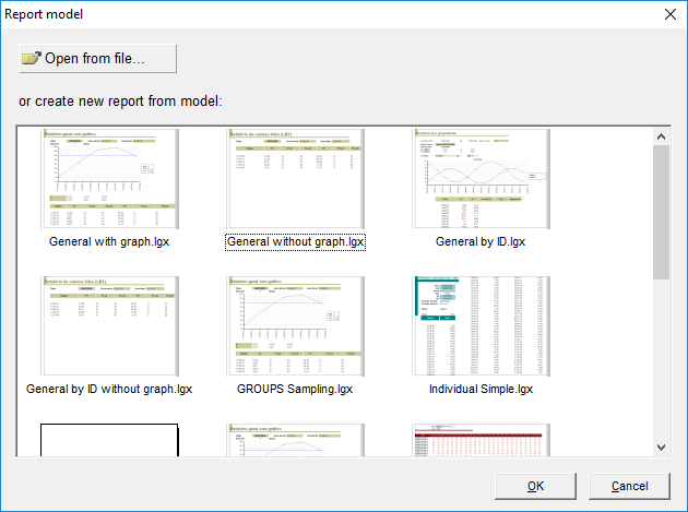
Set a name for the system report. It will be a file with a LGX extension that will contain a layout, formats, formulas, scripts and other reporting features.
(If you want to create or join a system report to the button, just click the right mouse over the button and select "Show this button's report”- see in step 3.)
It is possible to customize system reports in the SCADA system and also to create new templates.
Data and Reports - Edit.
See more details on system reports at the “Data and Report” or “Database” topic.
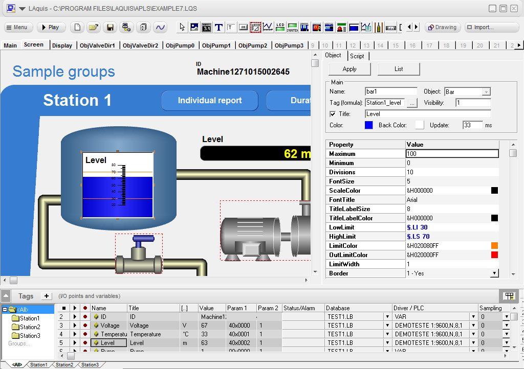
On top of the main SCADA system screen is located the HMI visual objects panel. On this panel the objects and HMI visual controls are designed and can be used as the interface for the user. These HMI objects can be displays, pictures, animations, controls, etc...
Select the desired object and place in the panel. Click on the object icon at the toolbar or choose the object in the right window (the “object tab” when no objects are being selected). Click on the HMI panel or drag the mouse pointer with the left button to draw the object.
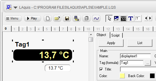
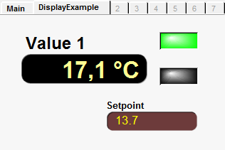
At the examples above, it was added an HMI object "displaytext", and a "Edit" object used to change values.
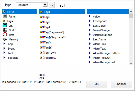
Each visual object may be associated with a SCADA tag. For that, click twice on the visual object at the panel, or select the "Formula" property of the object.
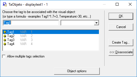
Select the SCADA tag to be associated with the visual object. In example above, the Tag1.
The title property at tag's spreadsheet can be used as the description and passed automatically to the visual object. (Tag's names also can be freely set, but must have no spaces and cannot be repeated in the same system group).
The visual objects has different
properties in SCADA system. In the following case was included a
button  .
By clicking once on it, a window at the right shows its
properties.
.
By clicking once on it, a window at the right shows its
properties.
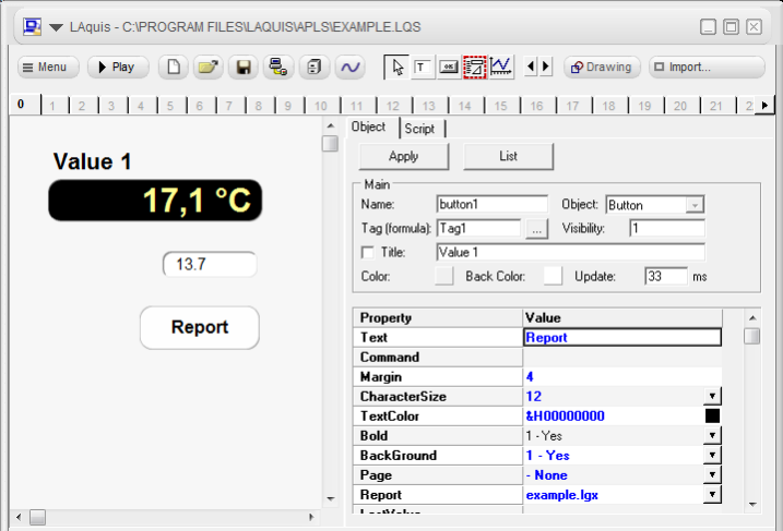

In the above example, these properties was changed: Text (with the value "Report") and system Report (set to the report lgx name). The Text property in this case is the title. If you want to create or associate a report to the button, just click the right mouse over the button and select "Show this button's report".
Another important property is Command. When the button is pressed the value of the associated SCADA tag will be the value of Command property. Also check Page properties, PopupPage and ChangeTag. See the button properties in topic “Visual Objects Examples”.
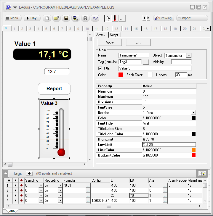
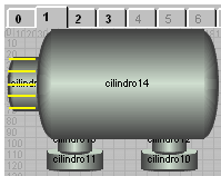
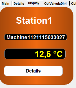
Example thermometer visual object. The upper and lower limits can be associated to the worksheet.

To import ready examples through the Import button ...
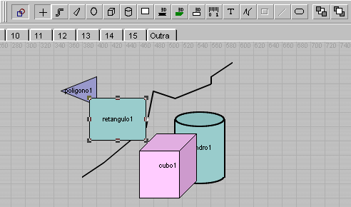
To create new vector objects in SCADA:

Draw at the panel pages using vector objects by "drawing” button
Instead of the page numbers may be used page names.
Example:
Pagename1;Pagename2;Pagename3 0=Pagename1;1=Pagename2
etc...
Before learning how to create new objects in SCADA system, it is needed to understand two concepts: Drawing vector objects and PageObject.
 SCADA
Drawing objects:
SCADA
Drawing objects:To draw in the panel using
vector objects click on the button. .
More details
of vector objects see the topic Drawing
objects .
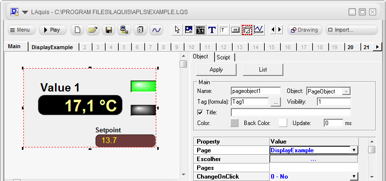
 PageObject:
Defines groups of HMI objects based
on a standard SCADA system panel. One way to do this is using the
PageObject object. It is possible to create an object with a group of
objects based on a standard panel. One way to do this is using the
PageObject .
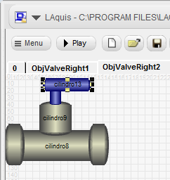
Set the objects on panel page (from page 1)
Associate the object PageObject to a tag or group.
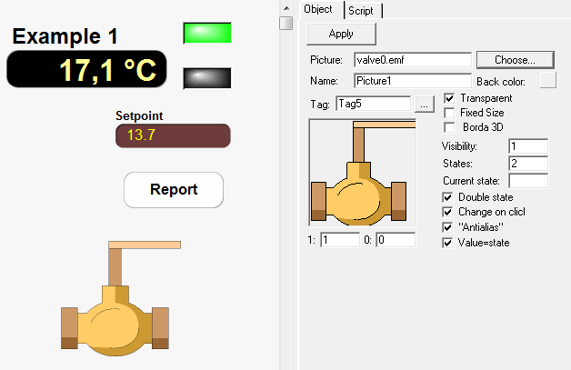
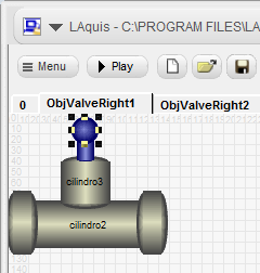
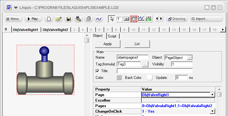
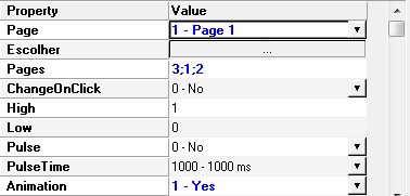
In the example below object Picture is configured as a button with animation. (Property Double State unchecked):
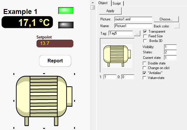
When the SCADA system is executed this visual object also will act like a button (property ChangeOnClick). Clicking on this object, the SCADA tag state associated with it will be changed to values switching between 0 and 1. But when the property Current State became 1 then the object enter in a animation state switching states from 1 to the maximum number of states. Picture name also must have the format <name><state>.emf or .bmp. In this case, motor1.emf e motor2.emf. It can be used used too a gif animated file. Nevertheless set the maximum number of states.
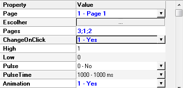
If its desired user intervention to change SCADA tag state set property ChangeOnClick.
More details about visual objects see the topic Visual Objects.
Scripts are sequences of instructions or programs used to customize the SCADA system application's actions to meet the process. They are executed within the available events in the system.
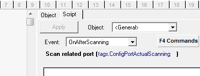
Select an object, click on the Script tab text. Enter, for example, Tag(“tag5”) = 1.
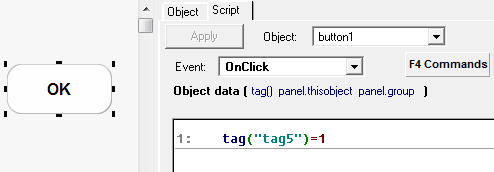
Tag motor will receive the value 1.
Note that a simple operation like this, used in these examples do not necessarily require a script - this sample is just for understanding purposes. Same operation could be done, just setting in the button object, Command property to 1.To access some of the script functions press F4.
Tags can be divided into groups. These groups may be stations, equipment, modules, machines, units, plants, etc ... SCADA tags names can be equal to each other, just by changing the groups and addresses.
PANELS:Generally, in the SCADA system, there is no need to develop a panel for each group if the SCADA system tags are equal or similar. If the panel is the same, and changes only addresses / tags groups, just create one panel. Once set the panel it may be associated in real time for any of the groups. This also applies to database and system reports.
DATABASE:
The database in the SCADA system is recorded by group. It is not necessary to create a different database for each group. The existence of several groups with the same bank, these groups will automatically be stored in parallel as follows: each record will have a field for each tag name and the group name is recorded in GROUPNAME field. At the system report, they can be displayed individually or in groups. See the examples below.
Example 1: Click the menu New - Example with groups. If you want to use this example to start the development of your application. Just select the example with groups, save and reset the SCADA tags, panels and system reports as required.
Example 2: Step by step manual (10 steps):
1 - Create a new blank application. (Menu New - <blank>)
2 - Click with the right mouse button on the groups list, left side of the SCADA tags spreadsheet.
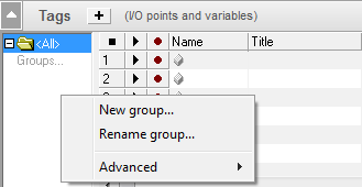
Optionally create tags VAR in SCADA to represent the group, equipment, unit, central, module, product, etc ... (In the example above ID)
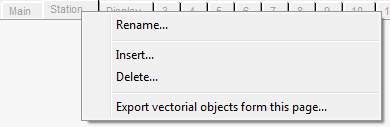
Rename the group if needed. Click the with the mouse right button on the group's tab, and select the "Rename group ..." option.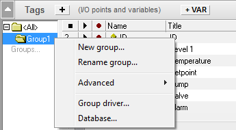
6 - To repeat or duplicate the groups, click with the mouse right button on the group's tab, select the "Advanced " option - "Duplicate groups ...".
Type the number of groups to be added based on the current group and click OK.Set the correct SCADA tags parameters for each group. Addresses, names, etc ... In general keep the same database name, for all groups. In the database, the internal GROUPNAME field will automatically differentiate the database's records.
Example:
7 - Now set a default panel in the SCADA system for one group. Set names for the panel pages. Click with the mouse right button on the page's tab, and select the Rename option. Example:
Example:
In the main page of the SCADA system, in this example named "Main", place buttons with the properties. Page with the value "Station" and ChangeTag with the property "1 - Yes". Associate each button with the desired group.
Example:
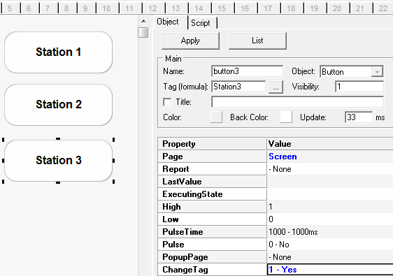
In execution mode, when the user clicks on one of these buttons, the page "Station" will be shown, and its objects automatically associated with the group.
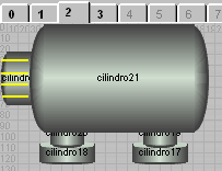
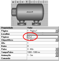
Instead of creating buttons, you can create custom objects with information from each group. Use in this case PageObject.
Example:
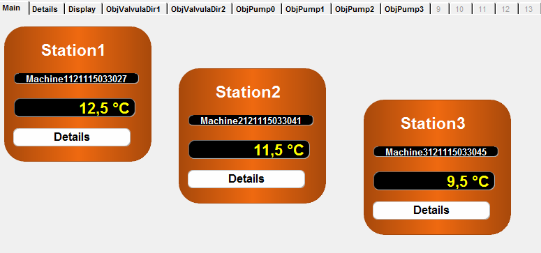
It has Page and ChangeTag properties set.
9 - Database: Use the same database name in the SCADA system, for all groups. Automatically the internal GROUPNAME field will differentiate the records in database.
Plays this application at least once. The system will create the database. Then stop the application.
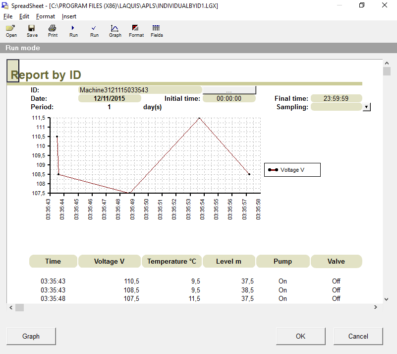
In this example, to ensure that the field (tag) ID is a text, click on the menu "Data and Reporting" - "Edit Database". Click on the “Fields”. ID field type set to 1 - Text.
10 - Report: After stored some data in SCADA system database, create a Button, click with mouse right button over it, select "Show this button's report" option.
Select in this case, for example, "General by ID" template, etc ....
Best new updated step by step of LAquis SCADA is in this link: