MODBUS RTU driver
First, you need to select the cells in the “Driver / PLC” column of the tags that will communicate with the equipment in the MODBUS RTU protocol.
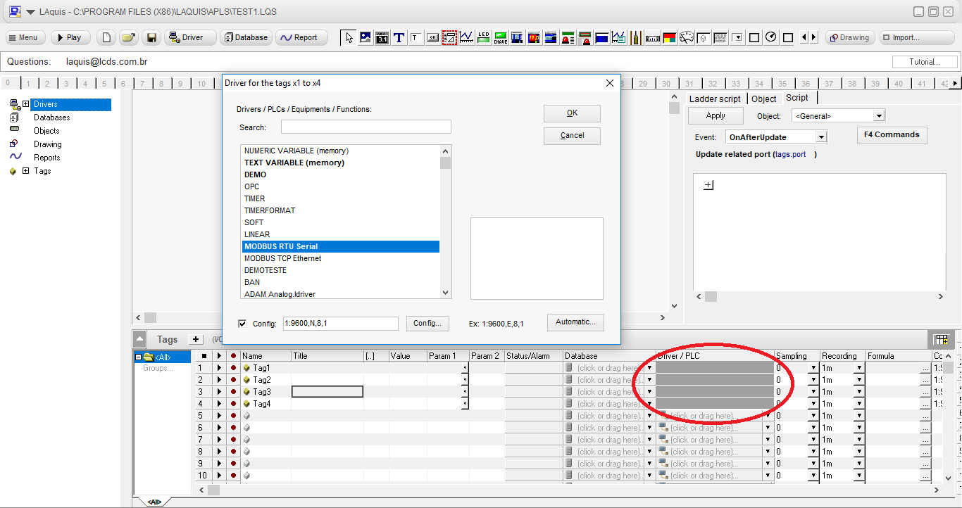
After that, the “Driver” window will open .
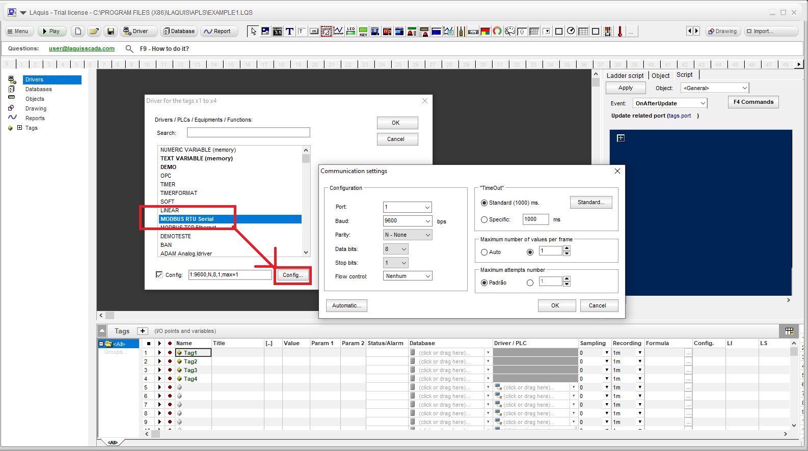
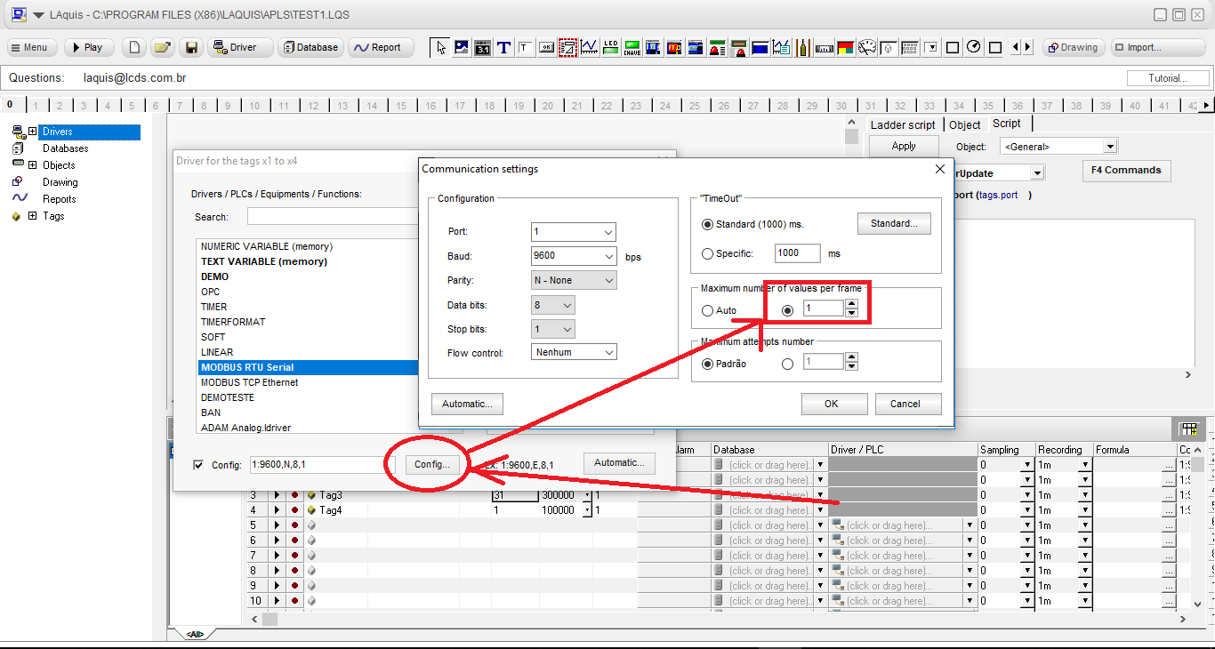
Select the “MODBUS RTU Serial” driver.
To configure it, click “Config” in the Driver window, and this procedure will open the “Communication settings” window, where you can configure the serial communication port and parameters (port, baud, parity, data bits, stop bits, etc…).
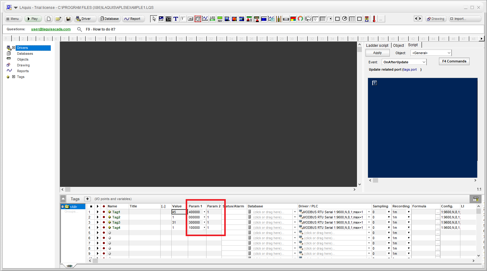
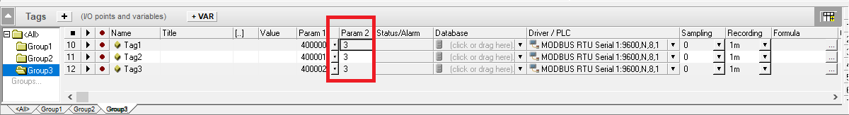
 In the Param2 column, place the node (address) from 1 to 255 of the equipment:
In the Param1 column , enter the addresses of the PLC variables.
Param1 format :
Example: 400000
MODBUS has 4 types of addresses with the following formats
4nnnnn
0nnnnn
3nnnnn
1nnnnn
where nnnnn is the address number, example 401008
The first digit is the type of the address.
4 – Holding Register – analog values in WORD (2 bytes) values ranging from -32768 to 32767 with the possibility of writing
Example: 401008
0 – Coil – digital values 0 or 1 with writing possibility
Example: 000004
3 – Input Register – analog values in WORD (2 bytes) values range from -32768 to 32767 read-only
Example: 300012
1 – Discrete input – digital values 0 or 1 read-only
Example: 100003
If the address is in hexadecimal, use 0x in front plus four hex digits, example: 40x000E
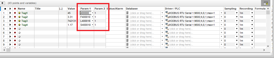
 Formats for analog numbers. A letter is used before the address.
Examples:
W400000 – WORD 2 bytes without sign, 0 to 65535
L400000 or I400000 – LONG 4 bytes with sign -2147483648 .. 2147483647
D400000 or J400000 – DOUBLE WORD 4 bytes with no sign 0 .. 4294967295
F400000 or S400000 or Y400000 – FLOAT 4 bytes
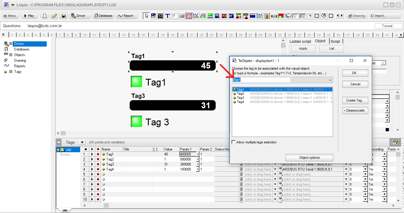
 Analog tags can be associated, for example, with the displaytext object for reading or LEditar for reading and writing. And in the case of the digital ones, they can be associated with the led object for reading or a key for reading and writing. Double click on the object and select the tag.
 Communication errors:
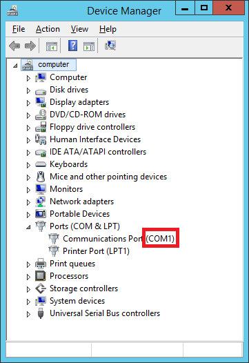
1 – Check in the device manager if the port used is available;
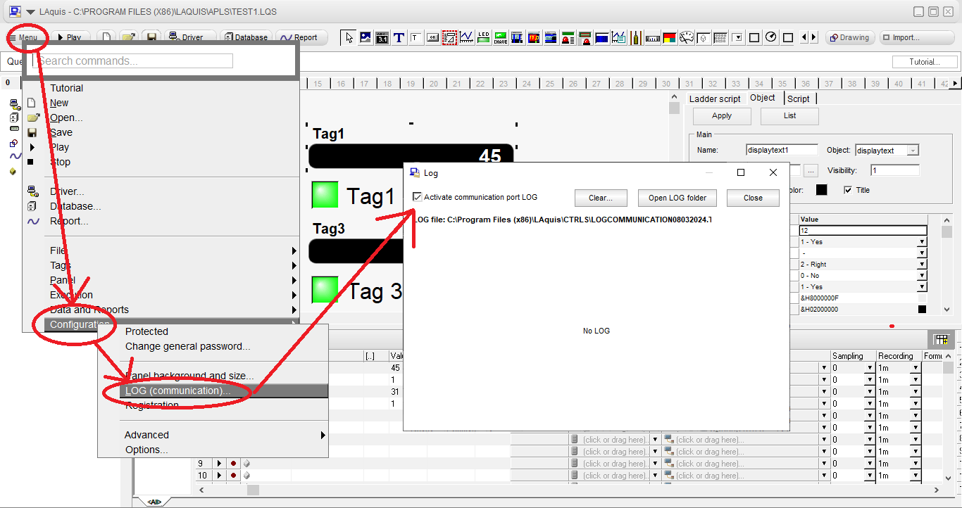
 2 – Activate the communication LOG and check if the equipment is responding, or if the port is being used by other software.
 3 – Sometimes the number of values per block exceeds what the PLC allows, causing an error in communication. To guarantee click on the Driver – Config – and select 1 value per frame:
 4 – Check the communication parameters are correct.
5 – Check that the equipment’s node address is correct in Param2 (value varies from 1 to 255).
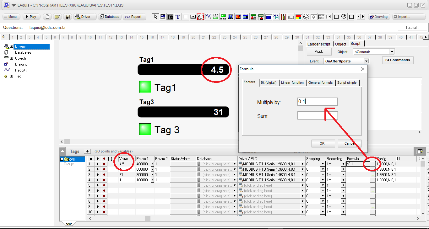
Formulas for converting values:
Click the button in the Formula column and enter the conversion factors.
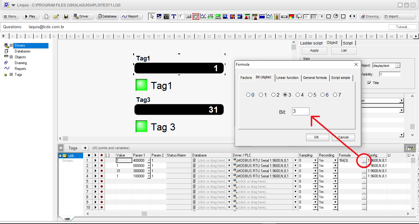
If the analog number is a set of bits, click on the Formula button and select the Bit on the Bit (digital) tab.
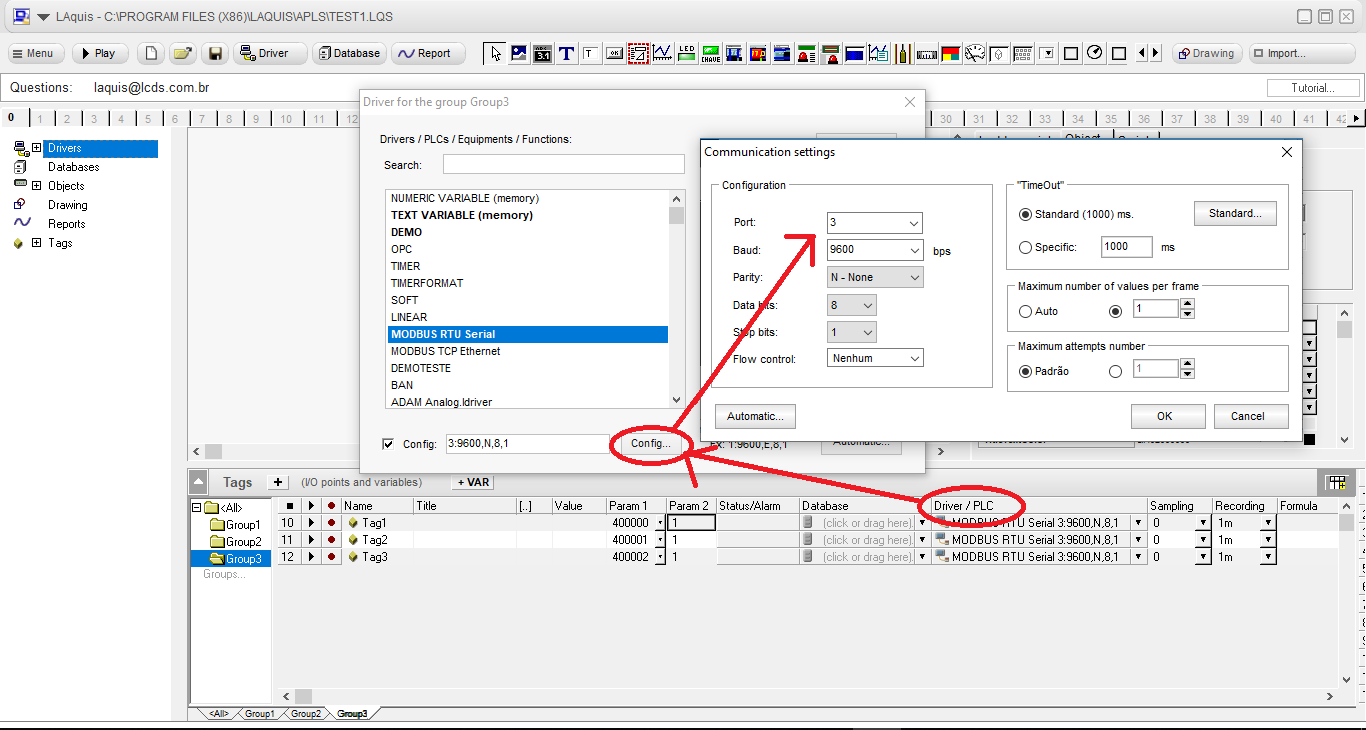
 To change the port of a complete group, goto the group and click on the Driver button or Driver/PLC column title:
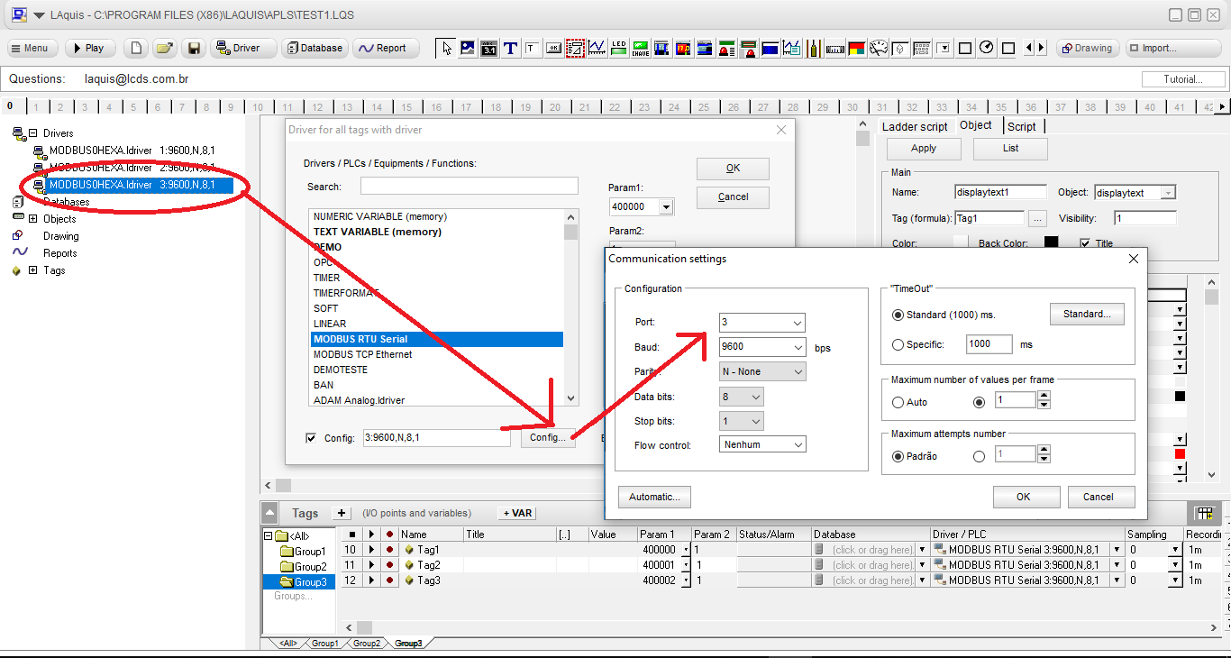
 If you want to change the driver for all groups that have the same communication parameters, use the left column:
Each group can be directed to a device node address from 1 to 255 if desired.
List of some devices that communicate via MODBUS protocol:
MODBUS protocol is a communication format standardized by Modicon, Schneider Electric and Modbus Organization. It can be used serially RS-232, RS-485, USB or TCP converter, Ethernet and Wifi.
MODBUS RTU is considered more for serial. MODBUS TCP is mostly used via Ethernet. The definition of frames was standardized via serial with address (1 byte), command (1 byte), record (2 bytes), quantity (2 bytes) and CRC (2 bytes). The MODBUS response depends on the type of command. Through the SCADA software, requests for values via MODBUS can contain an automatic quantity for each request, or it can be set to just one.