Step by step of the LAquis SCADA Arduino example:
First, download and install the last LAquis SCADA version as administrator, right mouse button on the installer file, execute as administrator (link here).
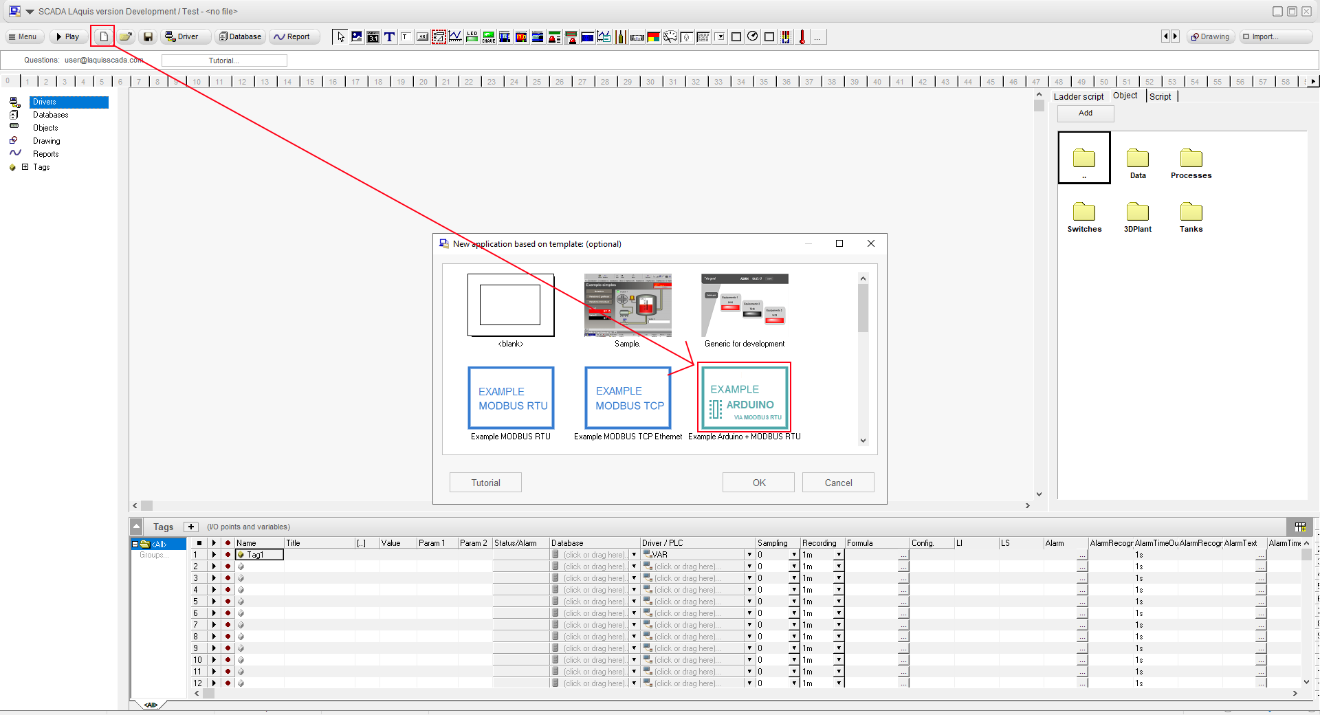
1 – Click no New button and select “EXAMPLE ARDUINO”.
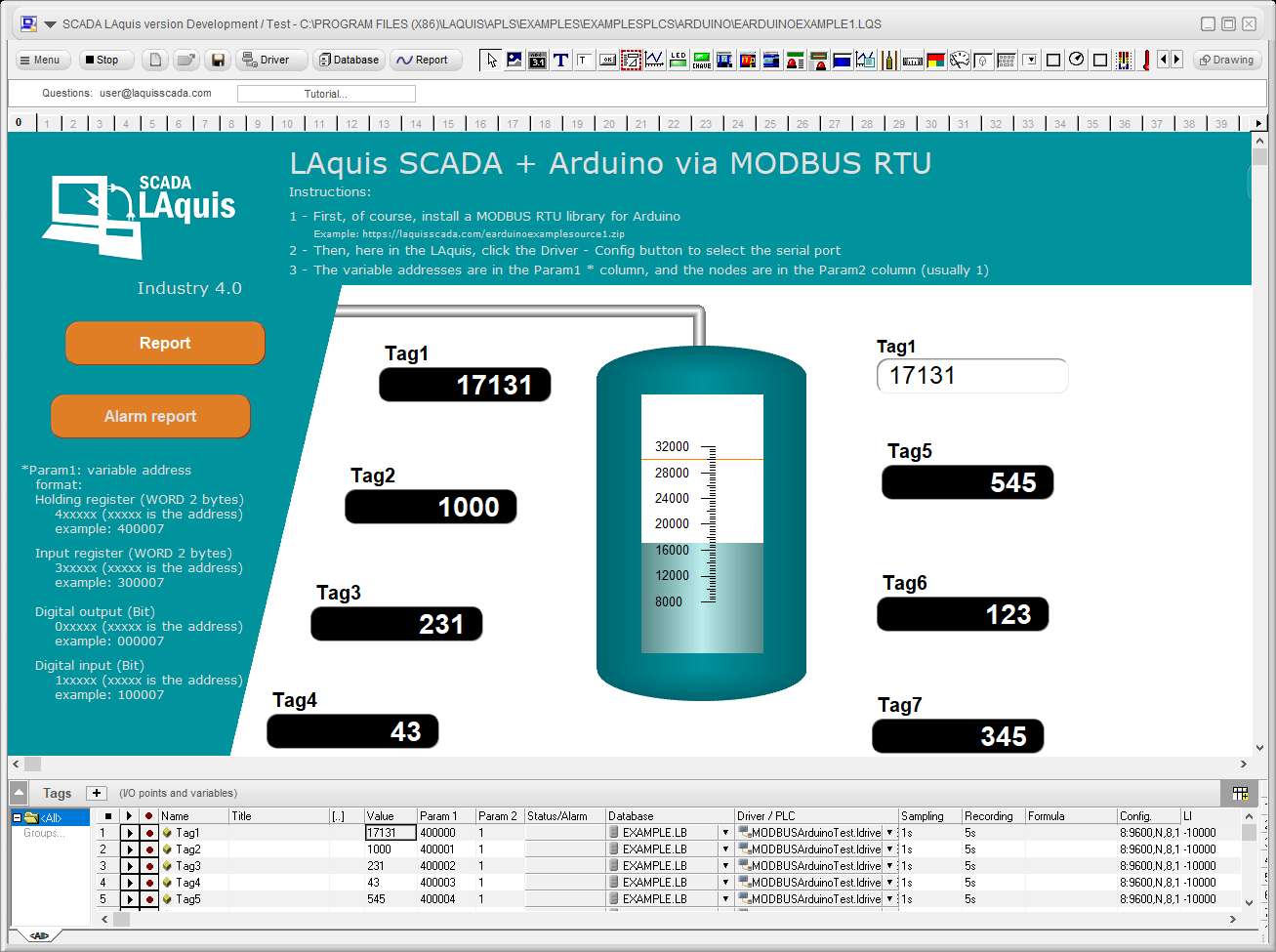
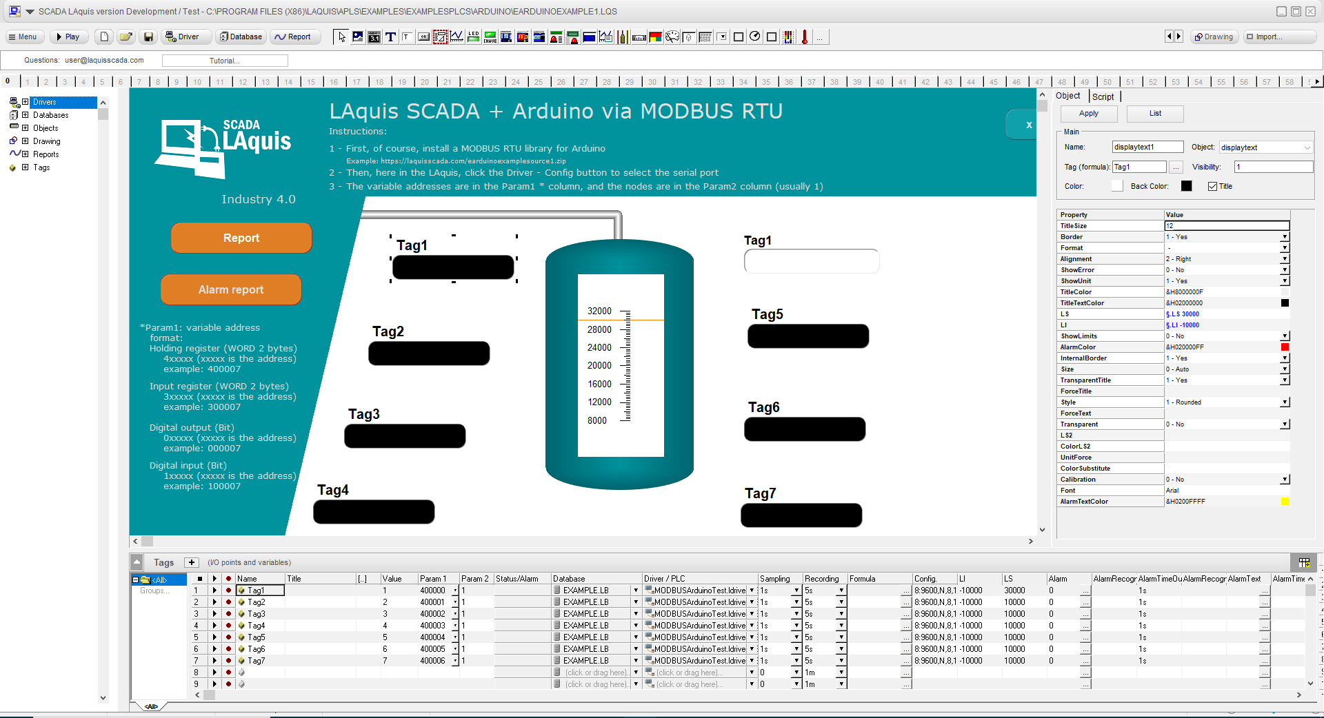
The Arduino example will be this, with a simple MODBUS RTU driver:
2 – Download and unpack the Arduino .ino project file from here:
https://laquisscada.com/earduinoexamplesource1.zip
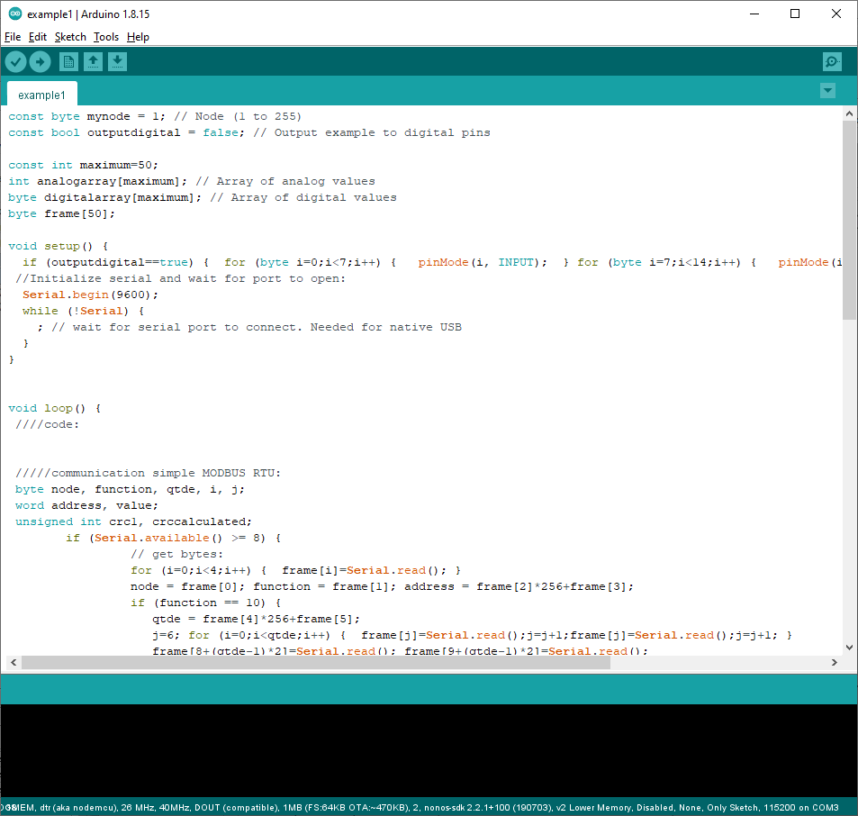
3 – Open the file example1.ino
4 – Compile and upload to the Arduino hardware.
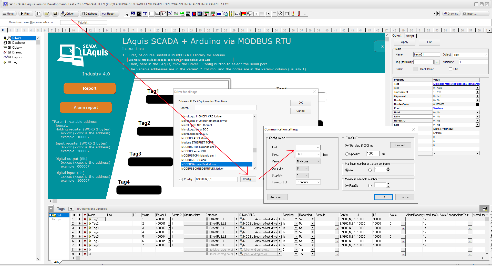
5 – Go to LAquis SCADA, click on Driver button and Config, select the serial COM port number. OK and OK.
6 – Click on “Play” button and test the communication.

About communication:
The used communication protocol, in this case, is MODBUS RTU.
To set digital outputs or read digital inputs, select in the Param1 column the “Coil” address (0, 1, 2, etc…).
To read or set analog variables, select the “Holding Register” address in the Param1 column. (400000, 400001, 400002, etc…).
Any issue in the communication, try to communicate and go to the Menu – Configuration – LOG Communication – Activate and check the frames sent and received in realtime.
About MODBUS RTU configuration:
More details on how to configure generic MODBUS RTU in LAquis SCADA link here:
MODBUS RTU – How to configure a communication via MODBUS RTU
About the Arduino .ino project file example:
This Arduino .ino project file example is a MODBUS RTU server.
Inside this Arduino .ino project file example, the analog variables are generic in a array called analogarray. Inside the .ino code, they can be associated with physical outputs or EEPROM flash memory. The digital variables are stored in the digitalarray array and already associated to the physical inputs and outputs.
Anyway, basic step by step to create generic applications in LAquis SCADA: